Colpitz oscillator: circuit and principle
The circuit that produces alternating and continuous waveforms is called oscillator. The waveform can be sine wave, square wave, etc. In this paper, according to its output frequency, the oscillator is divided into many types. The frequency of electronic oscillators can be controlled by their input voltage, so they are called voltage controlled oscillators.
There are many types of oscillators, but they are mainly divided into two categories: one is harmonic oscillator or linear oscillator, and the other is nonlinear oscillator. Non sinusoidal waveforms are generated by nonlinear oscillators, while linear oscillators generate sinusoidal waveforms. Under this linear oscillator category, there are different types of oscillators, such as Colpitts oscillator, feedback oscillator, phase-shift oscillator, Armstrong oscillator, negative resistance oscillator, delay line oscillator, pierce oscillator, beat oscillator and Wayne Bridge oscillator.
What is a Colpitts oscillator?
An amplifier that converts a DC signal as an input into an AC signal as an output (such as a square wave or sine wave) by using positive feedback and is driven by frequency conversion is called an oscillator. The oscillator using capacitor C and inductor L in the circuit is called LC circuit and belongs to linear oscillator. There are many ways to design the LC oscillator. Among those LC oscillators, the most familiar oscillators are Colpitts oscillator and Hartley oscillator. Among these two types of oscillators, Colpitts oscillator is the most commonly used oscillator. Edwin Colpitts invented the Colpitts oscillator in 1918.

Kolpitz oscillator theory
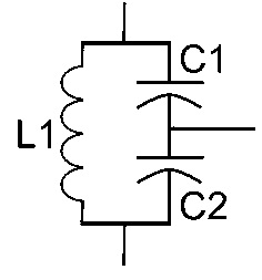
The oscillator forms an oscillation circuit by using two center tapped capacitors in series with parallel inductors and generates sinusoidal oscillation. The oscillation frequency can be obtained by considering the values of capacitors and inductors. In some aspects, this oscillator is similar to Hartley oscillator and different in some aspects.
In Hartley oscillator and Colpitts oscillator, the oscillation circuit connected between the collector and base of transistor amplifier to obtain sinusoidal output is the same. For this reason, the oscillator is called the electrical duality of Hartley oscillator.
The difference between the two oscillators is that the "tap autotransformer type inductor" is used in Hartley oscillator and the "capacitor voltage divider" network is used in Colpitts oscillator, that is, the simple Hartley oscillator uses tap inductance and Colpitts oscillator uses tap capacitance. The oscillator is specially designed for high frequency sinusoidal oscillation, and its RF range is from 10 kHz to 300MHz.
Colpitts oscillator circuit
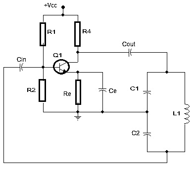
This is the circuit diagram of Colpitts oscillator. Many oscillator circuits that generate sinusoidal waveforms use LC resonant circuits, and no additional inductance is required except for some electronic circuits (such as RC oscillation, crystal oscillator and other oscillators).

When entering the circuit, there is a bipolar junction transistor (BJT), field effect transistor (FET) and operational amplifier, similar to other LC oscillators. The two capacitors C1 and C2 form a voltage divider, so the tap capacitor is used as a feedback source. Colpitts oscillator can provide good frequency stability. There is a re resistor in the circuit, which can provide good stability to deal with temperature fluctuations.
Capacitor "CE" is connected in parallel with resistor re. As a bypass capacitor, the capacitor provides a low reactance path for amplifying the signal. The circuit has an RC coupled amplifier and two resistors R1 and R2 constitute the voltage divider of the circuit.
Operating principle of Colpitts oscillator
Colpitts oscillator uses capacitor voltage divider network as feedback source. C1 and C2 form an energy storage circuit across the common inductance L. Therefore, when the power is turned on, the two capacitors C1 and C2 we see in the circuit begin to charge. After fully charged, they will be discharged through "L", which will cause damped harmonic oscillation.
At both ends of C1 and C2, the oscillating current generates an AC voltage. Although this discharge process is completely carried out in the capacitor, the capacitor will transfer electrostatic energy in the form of magnetic energy to the inductor, resulting in inductor charge. Similarly, when the inductance is discharged, the capacitor is charged. Therefore, oscillation will occur during the charging and discharging of inductors and capacitors.
Using the resonant frequency of the oscillation circuit, we can obtain the oscillation frequency. The energy storage circuit is energy storage, also known as energy accumulator. This is due to the continuous charging and discharging of the capacitor and inductor, and in order to obtain constant feedback, the two capacitors are combined together.
The resonant frequency of LC oscillation circuit is:
fr = 1/2π√(L1 * C)
Where "C" is the equivalent capacitance and "fr" is a resonant frequency.
C =(C1 * C2)/(C1 + C2)
The transistor amplifier configuration is an ordinary emitter amplifier 180 degrees out of phase with the input signal. An additional 180 degree phase shift is required. For this purpose, two capacitors are connected in series with the induction coil, resulting in a total phase shift of 360 degrees or 0.
Based on C1 and C2 values, the amount of feedback depends on. The feedback voltage can be adjusted by changing the value of the capacitor. If the feedback is small, the circuit will not oscillate. If the feedback is large, the output sine wave will be distorted. Based on the capacitance ratio of C1 and C2, the feedback is extended.


