Calculation of power-on time in RC resistance-capacitor power-on reset circuit developed by Dongguan MCU
Calculation of power-on time in RC resistance-capacitor power-on reset circuit developed by Dongguan MCU
This article introduces a method of calculating the time of an RC circuit.
Wen Shagull
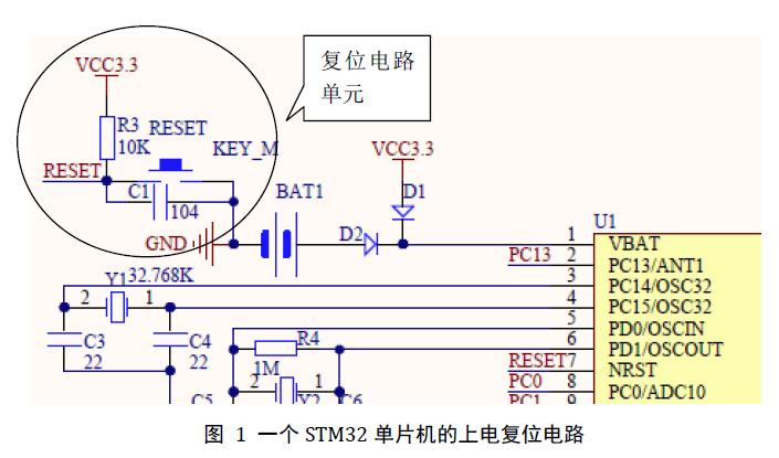
I often do projects on the development of single-chip microcomputer systems and their circuit boards here. In many of the smallest single-chip microcomputer systems, a very important circuit unit is the power-on reset circuit, such as 51 and STM32F103 single-chip microcomputers. In the past, I didn't think much about it when I was doing the design. Just follow the circuit recommended by the manufacturer and draw the gourd, and the effect is good without any problems.

However, recently I saw an information about the introduction of the RC power-on reset circuit, which talked about the calculation of the time for the voltage of the circuit to rise to a certain point, which I found very useful. For example, for a single-chip microcomputer, if the reset time is too long, and there are other peripherals, such as the display screen, it may cause the display screen to flicker after booting, which may not give the user a very good experience. So, let's share the calculation method of the time when the voltage reaches a certain point in this RC circuit to facilitate the design of designers or electronic enthusiasts.

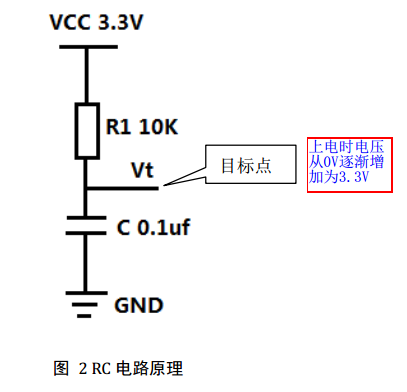
In this RC circuit, due to the instability of the power supply and the blocking effect of the capacitor C at the beginning of the power supply, the capacitor C can be regarded as a short circuit, so at this time Vt=0V, if Vt is connected to the STM32 microcontroller at this time At this time, the microcontroller will reset. Later, due to the gradual stability of the power supply and the charging and discharging effects of the capacitor, the capacitor gradually changed from a short circuit to an open circuit, and finally Vt=VCC=3.3V. However, the process of Vt from V0=0V to 3.3V is not achieved overnight, but a gradual rise process, which takes a certain amount of time.
Make an assumption: To make Vt=2.0V, set the time it takes for Vt to go from 0V to 2.0V when the power is turned on as t.
那么由公式: t=RxCxLn[(VCC-V0)/(VCC-Vt)]
=(10x103)x(0.1x10-6)xLn[(3.3-0)/(3.3-2.0)]
=0.931x10⁻³s=0.931ms
Among them, Ln is the natural logarithm, which is the logarithm with the constant e as the base. This can be calculated in the "scientific" mode in the calculator on the computer.
In other words, at this time, the microcontroller will reset immediately after the circuit is powered, and the microcontroller will work normally after 0.931 milliseconds. This parameter is the basis of the design, and the value of RC can be controlled to change to optimize the design.


